Camera models
This post give an introduction to various camera models, and specifically focuses on the pinhole camera model.
Camera models
Thin Lens Model
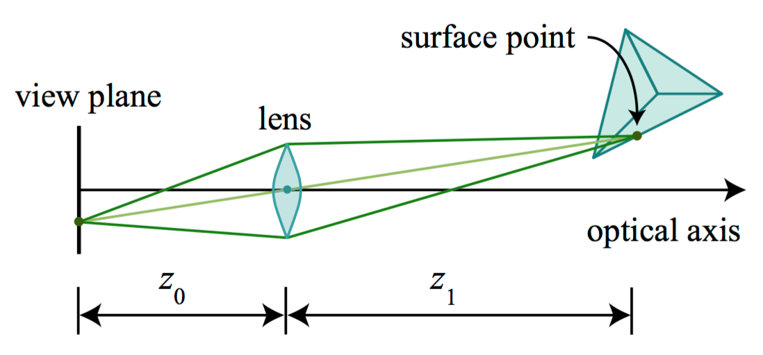
Most cameras use a lens to focus light onto the image plane so that enough light can be captured in a short period of time. Lens models can be quite complex, however, we can consider the simplist case, known as the thin lens model. In this model, light emmited from a single scene point travelling along different paths converge at a point behind the lens. This phenomena is governed by focus length, which is defined as the distance behind the lens to which rays from infinitely distant source converge in focus.

If \(z_1\) is the distance from the center of the lens to a surface point, then for a focal length \(\|f\|\), the rays from that surface point will be in focus at a distance \(z_0\) behind the lens center, where \(z_0\), and \(z_1\) will satisfy the thin lens equation:
\[\frac{1}{|f|}=\frac{1}{z_0}+\frac{1}{z_1} \]
Pinhole Camera Model
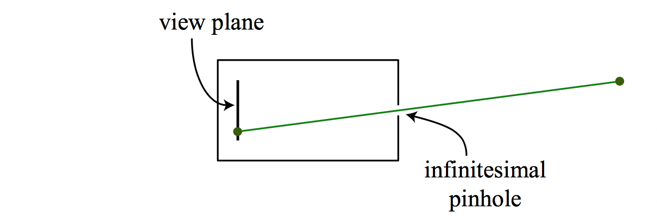
A pinhole camera is an idealization of the thin lens as aperture shrinks to zero. Light from a point travels along a single straight path through a pinhole onto the image plane. The object is imaged upside-down on the image plane.

Camera projections
Perspective Projections
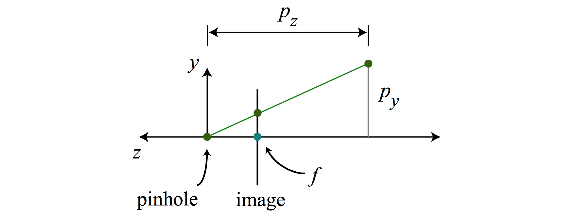
Consider a point \(\mathbf{X}(X, Y, Z)\) in 3D space with tthe camera center at the origin. The projection onto the image plane is \(\mathbf{x}(x, y, z)\), where \(x = \frac{f}{Z}X\). This is perspective projection.

Two important properties:
- Perspective projection preserves linearity;
- Perspective projection does not preserve parallelism.
Orthographic Projections
For objects sufficiently far away, rays are nearly parallel, and variation in \(Z\) is insignificant.
In this case, \(y = \alpha Y\), for some real scalar \(\alpha\). This is orthographic projection.

Camera coordinate system

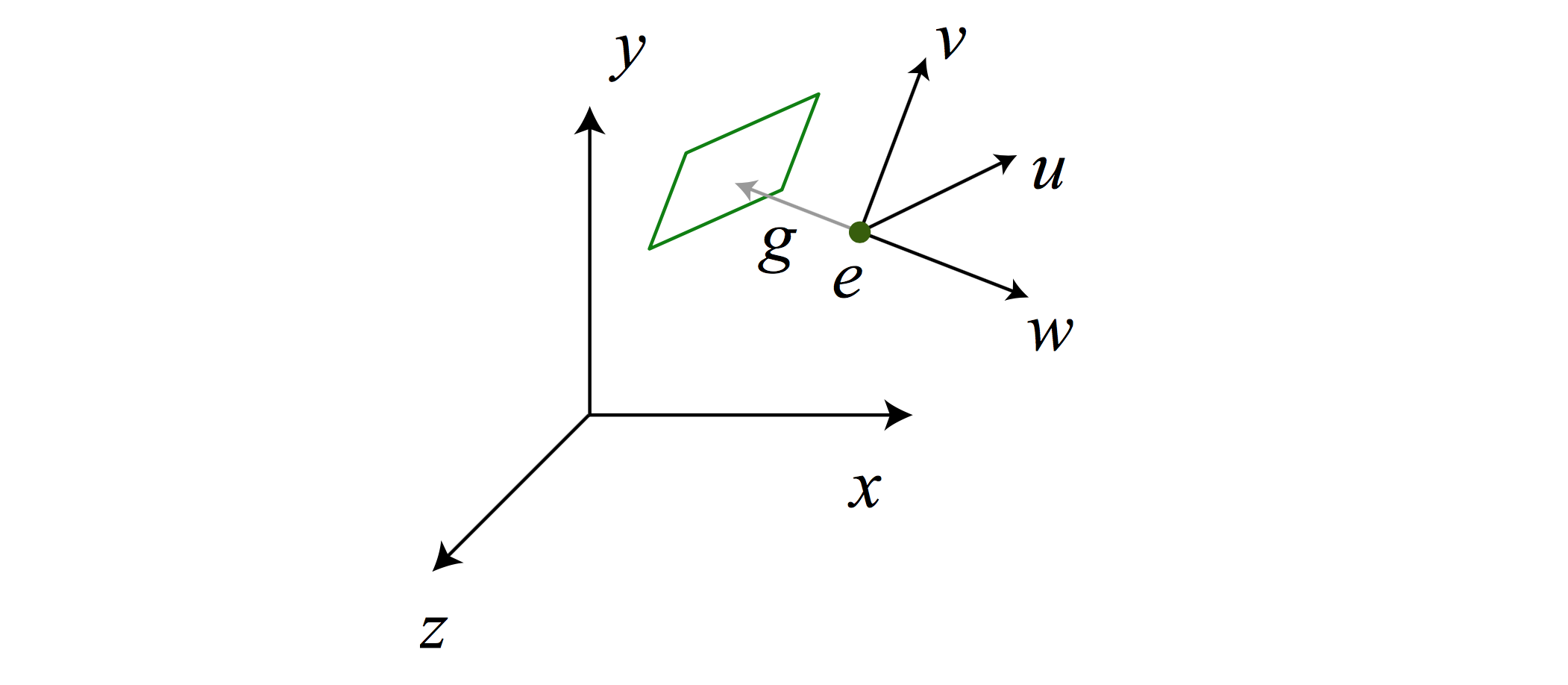
The center of projection \(e\) is the origin of coordinate system \(uvw\). Let \(\vec{g}\) is the optical axis, also the gaze direction, so the optical axis is
\[\vec{w}=-\frac{\vec{g}}{|\vec{g}|}\]
In order to determine \(\vec{u}\) and \(\vec{v}\), we first define the “up” vector \(\vec{t}\) as \((0, 1, 0)\). Then, \(\vec{u}\) is perpendicular to both \(\vec{w}\) and \(\vec{t}\), and \(\vec{v}\) is perpendicular to \(\vec{w}\) and \(\vec{u}\).
\[\vec{u}=\frac{\vec{t} \times \vec{w}}{|\vec{t} \times \vec{w}|}\] \[\vec{v} = \vec{w} \times \vec{u}\]
We can define a camera coordinate system based on these three vectors, where 3D points are represented w.r.t. the camera’s position and orientation.
Now we know how to represent the camera coordinate system within the world coordinate system, we need to explicitly formulate the rigid transformation between these two coordinate systems.
It’s not hard to show that for a point \(\mathbf{X_c}(X_c, Y_c, Z_c)\) in the camera coordinate system, the corresponding point in the world coordinate system is
\[\begin{align} \mathbf{X}_w &= \vec{e}+X_c \vec{u} + Y_c \vec{v} + Z_c \vec{w}\\ &= [\vec{u} | \vec{v} | \vec{w}]\mathbf{X}_c + \vec{e}\\ &= R_{cw}X_c + \vec{e} \end{align}\]We also need to find the inverse transformation, i.e., from world to camera coordinates. We note that that matrix \(R_{cw}\) is orthonomal. Because \(\vec{u}, \vec{v}, \vec{w}\) are unit vector that are perpendicular to one another. Therefore, \(R_{cw}^T R_{cw}=R_{cw}R_{cw}^T=I\). The inverse matrix \(R_{wc}\) is
\[\begin{align} \mathbf{X}_c = R_{cw}^T(\mathbf{X}_w - \vec{e}) \end{align}\]In inhomogeneous coordinates, we have \(R_{cw}=[\vec{u} | \vec{v} | \vec{w}]\) , and \(R_{wc}=\left[\begin{matrix} \vec{u}^T \\ \vec{v}^T \\ \vec{w}^T \end{matrix}\right]\)
In homogeneous coordinates, we have \(\hat{R}_{cw}=\left[\begin{matrix} R_{cw} & \vec{e} \\ \vec{0}^T & 1 \end{matrix}\right]\) , and \(\hat{R}_{wc}=\left[\begin{matrix} R_{wc} & -R_{wc}\vec{e} \\ \vec{0}^T & 1 \end{matrix}\right]\)