Camera visualization in Matlab
I read somewhere that to be more efficient in a long run when it comes to implementing a library, the first thing you should implement is the code that does visualization. To 3D computer vision, the single most important or common place component is probably the camera. This is what we are going to do here.
Visualization


% example code to visualize N synthetic cameras
close all;

N = 15;
ang = 2 * pi / N;
radius = 300;
f = 1400;
w = 640;
h = 480;

for i = 1 : N
    cos_ang = cos(i * ang);
    sin_ang = sin(i * ang);
    R = [-sin_ang,  cos_ang, 0;...
          0,        0,      -1;...
         -cos_ang, -sin_ang, 0];
    c = radius * [cos_ang, sin_ang, 0]';

    % implementation 1
    Rt = [R, -R*c];
    drawCamera(Rt, w, h, f, 0.05, 2);

    % implementation 2
%     K = [f 0 w/2; 0 f h/2; 0 0 1];
%     t = -R*c;
%     draw_camera(K, R, t);

    % implementation 3
%     K = [f 0 w/2; 0 f h/2; 0 0 1];
%     camera(i).w = w;
%     camera(i).h = h;
%     camera(i).K = K;
%     camera(i).R = R;
%     camera(i).c = c; % camera center in world coordinate system
end

% showcamera(camera);

xlabel('x'); ylabel('y'); zlabel('z');
axis equal;
view(0, 30);
title('implementation 2');
First implementation
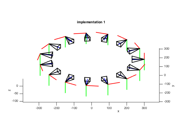
The first implementation comes from the SFMedu2 by Dr. Jianxiong Xiao. Assume that the focal length is \(f\), the coordinates of the center of projection and the four corners of the images plane in the camera coordinate system is: \((0, 0, 0)\), \((-\frac{w}{2}, -\frac{h}{2}, f)\), \((\frac{w}{2}, -\frac{h}{2}, f)\), \((\frac{w}{2}, \frac{h}{2}, f)\), \((-\frac{w}{2}, \frac{h}{2}, f)\). Points on the axes of the camera coordinate system are: \((f, 0, 0)\), \((0, f, 0)\), \((0, 0, f)\).
The next step is to transform these point from camera coordinate system to world coordinate system
\[\begin{align} \begin{bmatrix} X_c \\1 \end{bmatrix} &= \begin{bmatrix} R_{wc} & T_{wc} \\ \vec{0}^T & 1 \end{bmatrix} \begin{bmatrix} X_w \\1 \end{bmatrix}\\ \left[\begin{matrix} X_w \\1 \end{matrix}\right] &= \left[\begin{matrix} R_{wc} & T_{wc} \\ \vec{0}^T & 1 \end{matrix}\right]' * \left[\begin{matrix} X_c \\1 \end{matrix}\right]\\ &= \left[\begin{matrix} R_{wc}' & -R_{wc}'T_{wc} \\ \vec{0}^T & 1 \end{matrix}\right] * \left[\begin{matrix} X_c \\1 \end{matrix}\right]\\ \leftrightarrow X_w &= R_{wc}'*(X_c-T_{wc}) \end{align}\]function drawCamera(Rt, w, h, f, scale, lineWidth)
% SFMedu: Structrue From Motion for Education Purpose
% Written by Jianxiong Xiao (MIT License)
% Xcamera = Rt * Xworld
V=[...
0 0 0 f -w/2 w/2 w/2 -w/2
0 0 f 0 -h/2 -h/2 h/2 h/2
0 f 0 0 f f f f];
V = V * scale;
V = R'*(V-repmat(T, 1, size(V, 2)));
hold on;
plot3(V(1,[1 4]),V(2,[1 4]),V(3,[1 4]),'-r','LineWidth',lineWidth); % plot x-axis
plot3(V(1,[1 3]),V(2,[1 3]),V(3,[1 3]),'-g','LineWidth',lineWidth); % plot y-axis
plot3(V(1,[1 2]),V(2,[1 2]),V(3,[1 2]),'-b','LineWidth',lineWidth); % plot z-axis
plot3(V(1,[1 5]),V(2,[1 5]),V(3,[1 5]),'-k','LineWidth',lineWidth); % center to up-left corner
plot3(V(1,[1 6]),V(2,[1 6]),V(3,[1 6]),'-k','LineWidth',lineWidth); % center to up-right corner
plot3(V(1,[1 7]),V(2,[1 7]),V(3,[1 7]),'-k','LineWidth',lineWidth); % center to lower-right corner
plot3(V(1,[1 8]),V(2,[1 8]),V(3,[1 8]),'-k','LineWidth',lineWidth); % center to lower-left corner
plot3(V(1,[5 6 7 8 5]),V(2,[5 6 7 8 5]),V(3,[5 6 7 8 5]),'-k','LineWidth',lineWidth); % image plane
hold off;
end
Second implementation
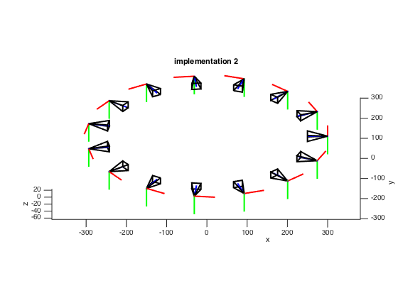
This implementation comes from the camera calibration toolbox implemented by Dr. Jean-Yves Bouguet. The key idea is the same, but instead of representing corners of image plane in the camera coordinate system, the corners are in the image plane, where the origin is at the up-left corner.
The image corners are defined in the image plane coordinate system, thus the center of the upper left corner pixel is \([0;0]\), the center of the upper right corner pixel is \([nx-1;0]\), the center of the lower left corner pixel is \([0;ny-1]\), and the center of the lower right corner pixel is \([nx-1;ny-1]\). \(nx\) and \(ny\) are the width and height of the image in pixel.
The first step is to transform these point from image plane coordinate system back to the camera coordinate system by left multiplying \(K'\).
\[\begin{align} K &= \begin{bmatrix} 1 & 0 & cc(1)\\ 0 & 1 & cc(2)\\ 0 & 0 & 1 \end{bmatrix} \begin{bmatrix} fc(1) & 0 & 0\\ 0 & fc(2) & 0\\ 0 & 0 & 1 \end{bmatrix} \begin{bmatrix} 1 & alpha_c & 0\\ 0 & 1 & 0\\ 0 & 0 & 1 \end{bmatrix}\\ K' &= \begin{bmatrix} 1 & -alpha_c & 0\\ 0 & 1 & 0\\ 0 & 0 & 1 \end{bmatrix} \begin{bmatrix} 1/fc(1) & 0 & 0\\ 0 & 1/fc(2) & 0\\ 0 & 0 & 1 \end{bmatrix} \begin{bmatrix} 1 & 0 & -cc(1)\\ 0 & 1 & -cc(2)\\ 0 & 0 & 1 \end{bmatrix} \end{align}\]The second step is the same as the one implemented above, transform points from the camera coordinate system to world coordinate system.
function draw_camera(K, R, t)
  alpha_c = K(1, 2);
  fc(1) = K(1, 1);
  fc(2) = K(2, 2);
  cc(1) = K(1, 3);
  cc(2) = K(2, 3);

  % for test purpose
  nx = 640; ny = 480; dX = 30; dY = 30;

  % step 1: image plane to camera coordinate system
  IP = 5*dX*[1 -alpha_c 0;...
             0  1       0;...
             0  0       1] *...
            [1/fc(1) 0       0;...
             0       1/fc(2) 0;...
             0       0       1] *...
            [1 0 -cc(1);...
             0 1 -cc(2);...
             0 0  1] *...
            [0 nx-1 nx-1 0    0;...
             0 0    ny-1 ny-1 0;...
             1 1    1    1    1];
  BASE = 5*dX*([0 1 0 0 0 0;...
                0 0 0 1 0 0;...
                0 0 0 0 0 1]);

  IP = reshape([IP;BASE(:,1)*ones(1,5);IP],3,15);

  % step 2: camera coordinate system to world coordinate system
  BASE = R' * (BASE - t * ones(1, 6));
  IP = R' * (IP - t * ones(1, 15));

  hold on;
  plot3(BASE(1,[1 2]),BASE(2,[1 2]), BASE(3,[1 2]),'r-','linewidth',2'); % x-axis
  plot3(BASE(1,[3 4]),BASE(2,[3 4]), BASE(3,[3 4]),'g-','linewidth',2'); % y-axis
  plot3(BASE(1,[5 6]),BASE(2,[5 6]), BASE(3,[5 6]),'b-','linewidth',2'); % z-axis
  plot3(IP(1,:),IP(2,:), IP(3,:), 'k-','linewidth',2);
end
Third implementation
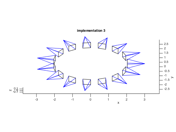
The third implementation comes from the Carving a Dinosaur. The biggest difference is that this implementation draws the corresponding image on the image plane.
function showcamera(ax,camera)
%SHOWCAMERA: draw a schematic of a camera
%
%   SHOWCAMERA(CAMERA) draws a camera on the current axes
%
%   SHOWCAMERA(AXES,CAMERA) draws a camera on the specified axes
%
%   Example:
%   >> cameras = loadcameradata(1:3);
%   >> showcamera(cameras)
%
%   See also: LOADCAMERADATA

%   Copyright 2005-2009 The MathWorks, Inc.
%   $Revision: 1.0 $    $Date: 2006/06/30 00:00:00 $

if nargin<2
    camera = ax;
    ax = gca();
end

scale = 1;
subsample = 16;

for c=1:numel(camera)
    cam_c = camera(c).c;

    hold on;
    % Draw the camera centre
    plot3(camera(c).c(1),camera(c).c(2),camera(c).c(3),'b.','markersize',5);

    % Now work out where the image corners are
%     [h,w,colordepth] = size(camera(c).Image); %#ok<NASGU>
    w = camera(c).w; h = camera(c).h; % for test

    imcorners = [0 w 0 w
        0 0 h h
        1 1 1 1];
    worldcorners = iBackProject( imcorners, scale, camera(c) );

    iPlotLine(cam_c, worldcorners(:,1), 'b-')
    iPlotLine(cam_c, worldcorners(:,2), 'b-')
    iPlotLine(cam_c, worldcorners(:,3), 'b-')
    iPlotLine(cam_c, worldcorners(:,4), 'b-')

    % Now draw the image plane. We will need the coords of every pixel in order
    % to do the texturemap
    draw_texture = 0;
    if ~draw_texture
        iPlotLine(worldcorners(:, 1), worldcorners(:, 2), 'k-');
        iPlotLine(worldcorners(:, 1), worldcorners(:, 3), 'k-');
        iPlotLine(worldcorners(:, 4), worldcorners(:, 2), 'k-');
        iPlotLine(worldcorners(:, 4), worldcorners(:, 3), 'k-');
    else
        [x,y,z] = meshgrid( 1:subsample:w, 1:subsample:h, 1 );
        pix = [x(:),y(:),z(:)]';
        worldpix = iBackProject( pix, scale, camera(c) );
        smallim = camera(c).Image(1:subsample:end,1:subsample:end,:);
        surface('XData', reshape(worldpix(1,:),h/subsample,w/subsample), ...
            'YData', reshape(worldpix(2,:),h/subsample,w/subsample), ...
            'ZData', reshape(worldpix(3,:),h/subsample,w/subsample), ...
            'FaceColor','texturemap', ...
            'EdgeColor','none'); % 'CData', smallim
    end
end
set( ax,'DataAspectRatio', [1 1 1] )

%-------------------------------------------------------------------------%
function X = iBackProject( x, dist, camera )
%IBACKPROJECT - backproject an image location a distance DIST and return
%   the equivalent world location.
if size(x,1)==2
    x = [x;ones(1,size(x,2))];
end

X = camera.K \ x;
normX = sqrt(sum(X.*X,1));
X = X ./ repmat(normX,size(X,1),1);
X = repmat(camera.c,1,size(x,2)) + dist * camera.R'*X;

%-------------------------------------------------------------------------%
function iPlotLine(x0, x1, style)
plot3([x0(1),x1(1)], [x0(2),x1(2)], [x0(3),x1(3)], style);