Structure from Motion Tutorial
Structure from Motion is like the holy grail of multiple view geometry. It is a process of estimating camera pose and retrieving a sparse reconstruction simultaneously. In this tutorial, I’ll discuss every step of this technique and provide detailed implementation using open3DCV. The source code can be found here.
Table of Content
- Test images
- Image IO
- Feature detection
- Descriptor extraction
- Feature matching
- Relative pose estimation
- N-view triangulation
- Bundle adjustment
- Two-view SfM
- N-view SfM
- Output
- Results
0. Test images
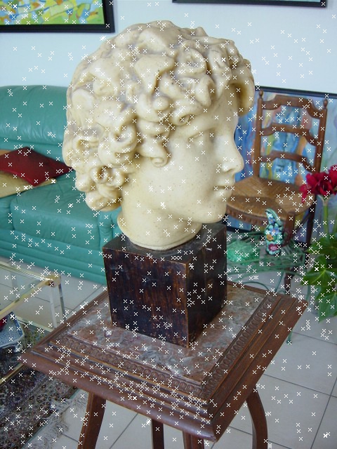
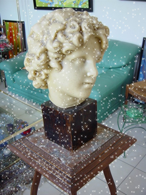
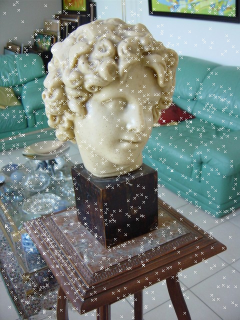
I used the bust images from Jianxiong Xiao’s SfM tutorial, and templeRing dataset from Middlebury mview datasets. The directory of the test images is
string idir = "/Users/BlacKay/Documents/Projects/Images/test/bust/";
string idir = "/Users/BlacKay/Documents/Projects/Images/test/templeRing/";
1. Image IO
The image naming convention follows that of PMVS. For instance, the first image is named as 00000000.jpg, the second is named as 00000001.jpg, and so on.
const int nimages = 10;
char iname[100];
vector<Image> images(nimages);
for (int i = 0; i < nimages; ++i)
{
    sprintf(iname, "%s/%08d.jpg", idir.c_str(), i);
    images[i].read(iname);
}
2. Feature detection
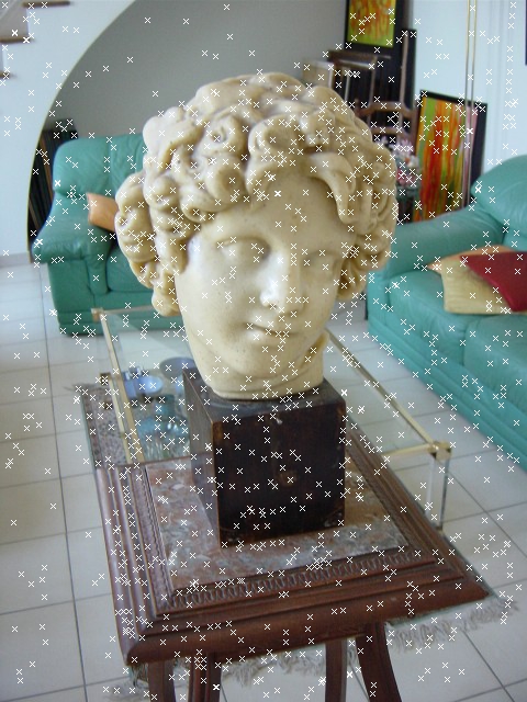
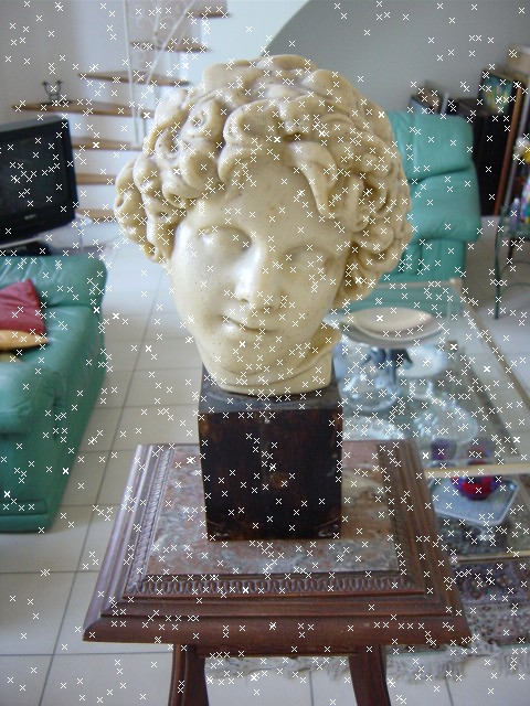
The currently implemented feature detector is SIFT detector, and more feature detectors are under development. The configuration class SiftParam needs eight parameters to configure both SIFT detector and descriptor, the first five is responsible for the detector while the last three is responsible for the descriptor. The datatype Keypoint is used to hold the detected keypoint.
SiftParams sift_param(3, 3, 0, 10.0f / 255.0, 1, -INFINITY, 3, 2);
Sift sift(sift_param);
vector<vector<Keypoint> > keys(nimages, vector<Keypoint>());
vector<vector<Vecf> > descs(nimages, vector<Vecf>());
for (int i = 0; i < nimages; ++i)
{
    sift.detect_keypoints(images[i], keys[i]);
    sift.extract_descriptors(images[i], keys[i], descs[i]);
    sift.clear(); // don't forget this
}
3. Descriptor extraction
Feature descriptor is extracted per keypoint, though theoretically, more than one descriptor is possible (at most 4). Currently, only SIFT descriptor is implemented, but more descriptors are under developments. The last three parameters of the SiftParam class is responsible for the configuration of the SIFT descriptor. Each descriptor is a 128 vector which is hold by a type Vec or Vecf. See the code above.
4. Feature matching
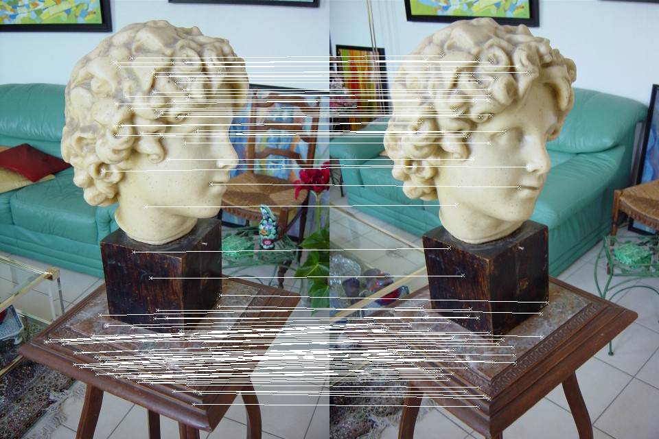
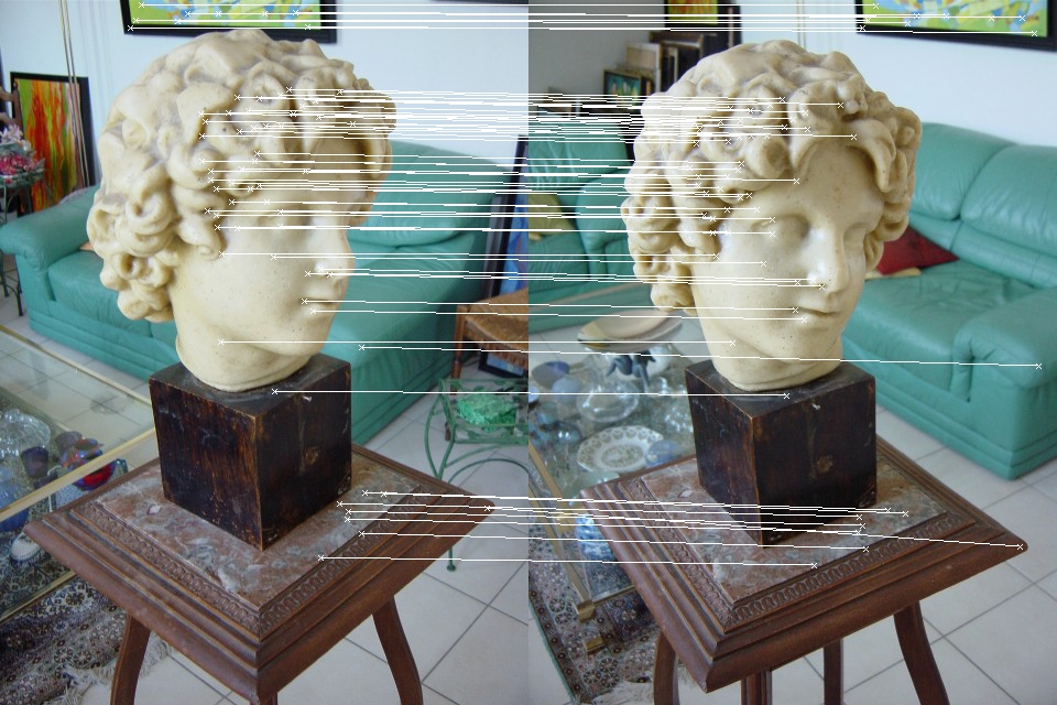
Once features have been detected and descriptors extracted in each image, the system matches features between each pair of images in the input image set. The number of image pairs is \(\binom{N}{2}\), where \(N\) is the size of the image set. Let \(\{f_I\}\) denote the set of features detected in image \(I\) and \(d(f_I^m)\) descriptor of feature \(f_I^m\). For each pair of images \(I\) and \(J\), the system considers each feature \(f_I^m\in \{f_I\}\) and finds its nearest neighbor \(f_J^n\in \{f_J\}\):
\[f_J^n = argmin_{f_J^p\in \{f_J\}} dist(d(f_I^m), d(f_J^p))\]where \(dist(\cdot, \cdot)\) is a user-specified distance metric. This brute-force approach can be replaced by using an approximate nearest neighbour library, such as FLANN, ANN, Nanoflann, and so on. To make the matching results more robust, a bi-directional verification is performed, which requires that \(f_I^m\) and \(f_J^n\) need to be among the top \(K\) matching points of one another. The information of a pair of matching keypoints is stored in a type DMatch, which is discussed below.
class DMatch
The datatype DMatch holds the information of a pair of correspondening features, and is defined as follows:
std::pair<int, int> ind_key_holds the indexes of the matching keypoints;std::pair<Vec2f, Vec2f> point_holds the 2D positions of the matching keypoints.
class DMatch
{
public:
    DMatch () {};
    DMatch (const int r_ikey1, const int r_ikey2, const float dist) :
        ind_key_(r_ikey1, r_ikey2), dist_(dist) {};
    DMatch (const int r_ikey1, const int r_ikey2, const Vec2f r_pt1, const Vec2f r_pt2, const float dist) :
        ind_key_(r_ikey1, r_ikey2), point_(r_pt1, r_pt2), dist_(dist) {};
    DMatch (const DMatch& match) :
        ind_key_(match.ind_key_), point_(match.point_), dist_(match.dist_) {};

    const float& dist() const;

    std::pair<int, int> ind_key_;
    std::pair<Vec2f, Vec2f> point_;
    float dist_;
};
class Pair
Before heading to the next section of estimating the relative pose of an image pair, we first define the most fundmental data structure used in pairwise image matching, which is named Pair. It stores everything regaring the two-view geometry, including matching features, fundamental matrix, essential matrix, relative rotation and translation, and so on. A brief summary of the class Pair and the declaration is as follows:
- camera indexes:
ind_cam_; - matching features:
matches_; - fundamental and essential matrix:
F_,E_; - intrinsics and extrinsics of the corresponding cameras:
intrinsics_mat_,extrinsics_mat_.
class Pair
{
public:
    Pair();
    Pair(const int cam1, const int cam2);
    Pair(const int cam1, const int cam2, const std::vector<std::pair<Vec2f, Vec2f> >& matches);
    Pair(const int cam1, const int cam2, const std::vector<DMatch>& matches);
    ~Pair();

    void init(const int ind_cam1, const int ind_cam2);
    void update_matches(const int* vote_inlier);
    void update_intrinsics(const float f, const int w, const int h);
    bool operator<(const Pair& rhs) const;
    float baseline_angle() const;

    std::vector<int> cams_;
    std::vector<DMatch> matches_;
    Mat3f F_;
    Mat3f E_;
    std::vector<Mat3f> intrinsics_mat_;
    std::vector<Mat34f> extrinsics_mat_;

};
See below some of the matching results:
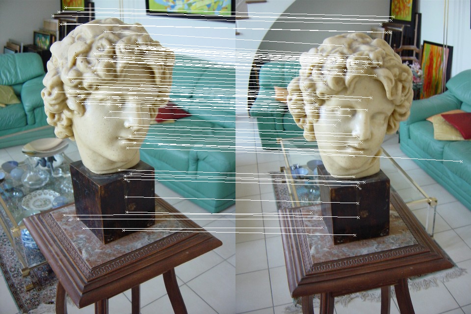
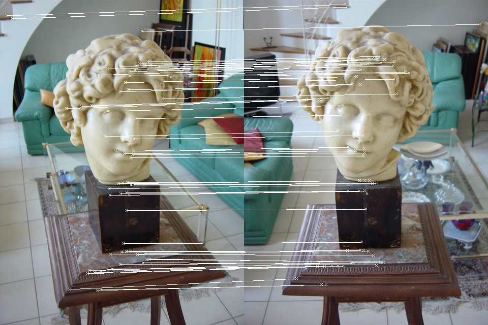
vector<Pair> pairs;
Matcher_Param matcher_param(0.6*0.6, 50);
Matcher_Flann matcher(matcher_param);
vector<vector<vector<DMatch> > > matches_pairwise(nimages-1, vector<vector<DMatch> >());
for (int i = 0; i < nimages-1; ++i)
{
  matches_pairwise[i].resize(nimages-(i+1));
  for (int j = i+1; j < nimages; ++j)
  {
    vector<DMatch>& matches = matches_pairwise[i][j-(i+1)];
    matcher.match(descs[i], descs[j], matches);
    matcher.matching_keys(keys[i], keys[j], matches);
    pairs.push_back(Pair(i, j, matches));
    string fname = odir+"matching"+to_string(i+1)+"_"+to_string(j+1)+".txt";
    write_matches(fname, matches);
    if ((false))
    {
      draw_matches(images[i], keys[i], images[j], keys[j], matches, odir+"matching"+to_string(i+1)+"_"+to_string(j+1));
    }
    cout << "Image (" << i+1 << ", " << j+1 << "): matches number: " << matches.size() << endl;
  }
}
5. Relative pose estimation
For each pair of images with sufficient number of matches/correspondences, a relative pose estimation is performed, which is followed by a triangulation step, a bundle adjustment step, and then various verification steps to check if this pair of images holds enough information for subsequent steps, or if the estimated relative pose is accurate enough. This step is a crucial part of two-view SfM, and is generally divided into two groups, one with calibrated cameras, or known focal length, and one with uncalibrated cameras, or unknown focal length.
Known intrinsic parameters
SfM using calibrated cameras is the most common case in practice since the camera intrinsics remain fixed unless manually changed. This is the case where euclidean (metric) reconstruction is possible, whereas in the uncalibrated case, only projective reconstruction is possible.
Estimate essential matrix
Essential matrix can be estimated using the 5-point algorithm + RANSAC. This approach is still under development since currently the Essential Matrix is computed from the estimated Fundamental Matrix, the underlying theory is as follows:
Estimate fundamental matrix
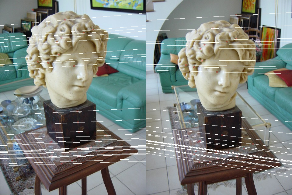
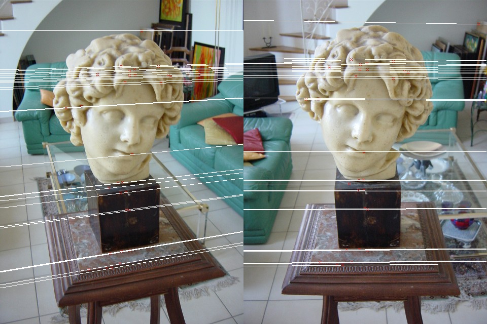
The Fundamental matrix can be estimated using the 7-point algorithm + RANSAC. I choose 7-point algorithm over 8-point algorithm because it requires less data thus less iterations are needed to achieve the same probability of inliers. The theory and implementation of the estimation of Fundamental matrix, RANSAC, and robust estimation of fundamental matrix using RANSAC are discussed in depth in the corresponding blog posts. The estimated matrices regarding the epipolar geometry are stored in the data structure Pair as mention previously. The source code of estimating fundamental matrix is as follows:
for (int i = 0; i < pairs.size(); ++i)
{
    // ------ image pair ------
    Pair& pair = pairs[i];
    int nmatches = static_cast<int>(pair.matches_.size());
    const int& ind1 = pair.cams_[0];
    const int& ind2 = pair.cams_[1];
    cout << "*******************************" << endl;
    cout << " 2-View SfM of image " << ind1+1 << " and " << ind2+1 << endl;
    cout << "*******************************" << endl;

    // ------ estimate Fundamental matrix ------
    vector<float> params(9);
    int *vote_inlier = new int[nmatches];
    Param_Estimator<DMatch, float>* fund_esti = new open3DCV::Fundamental_Estimator(1e-8);
    float ratio_inlier = Ransac<DMatch, float>::estimate(fund_esti, pair.matches_, params, 0.99, vote_inlier);
    std::cout << "ratio of matching inliers: " << ratio_inlier << std::endl;
    if (ratio_inlier < thresh_inlier_ratio)
    {
        delete [] vote_inlier;
        continue;
    }
    pair.F_ << params[0], params[3], params[6],
               params[1], params[4], params[7],
               params[2], params[5], params[8];

    // ------ other more code ------
}
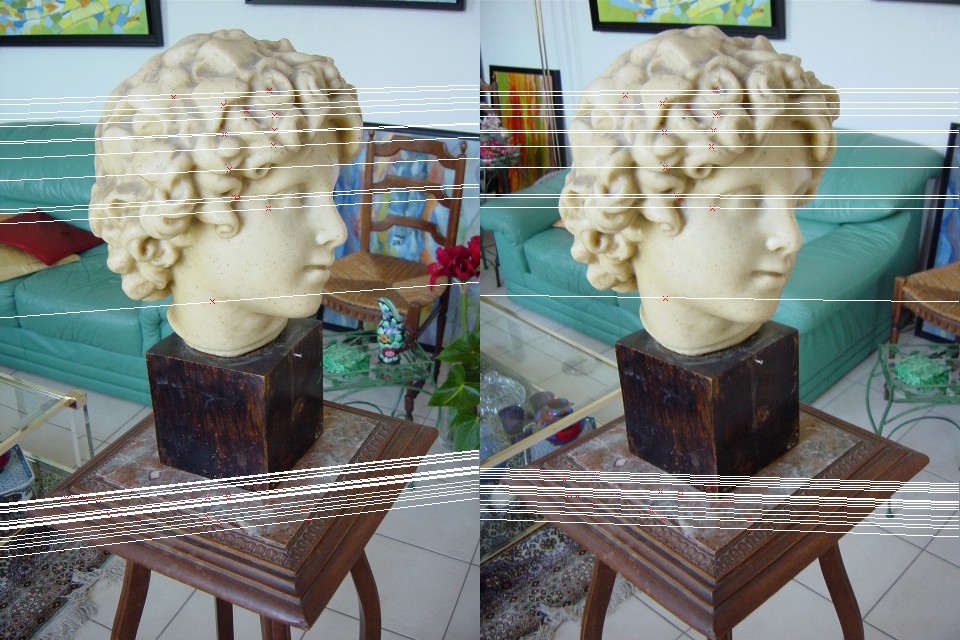
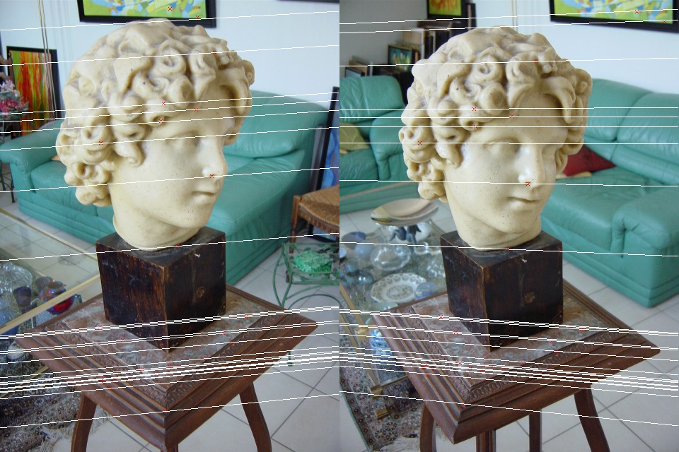
Rigid pose estimation from Essential matrix
We can estimate the relative position and orientation of two cameras from Essential matrix, the theory and implementation are discussed in depth in this post. The source code of estimating the rigid pose is as follows:
// ------ estimate relative pose ------
const float f = 1520.4;
const int w = 302.32*2, h = 246.87*2;
pair.update_intrinsics(f, w, h);
pair.E_ = pair.intrinsics_mat_[1].transpose() * pair.F_ * pair.intrinsics_mat_[0];
Rt_from_E(pair);
Unknown intrinsic parameters
This is the case where uncalibrated cameras are used, and the scene is reconstructed up to a projective projection. This section is still under development.
Estimate homography
[TBD]
Estimate focal length from homography
The detail of estimation of focal length from homography can be found here.
6. N-view triangulation
From calibrated cameras and correspondences, the positions of the 3D points can be estimated using N-view triangulation techniques. The theory and implementation of various triangulation techniques are discussed in depth in this post. Recall that we defined a data structure Pair for two-view case, a new data structure named Graph is defined for the N-view case.
class Graph
The class Graph is heavily used hereafter, it is a data structure that stores information of multiple cameras with sufficient amount of matching features, the corresponding camera poses/orientations, and a sparse 3D reconstruction, the detailed definition is as follows:
- number of cameras:
ncams_; - indexes of cameras:
ind_cam_; - intrinsics and extrinsics of cameras:
intrinsics_mat_,extrinsics_mat_; - point tracks:
tracks_. Each set of matching pixels across multiple images forms one track, which also corresponds to a single 3D point, i.e., each individual pixel in a track should be the projection of the same 3D point. It’s the N-view counterpart ofDMatch. - structure points:
structure_points_, a data structure holds information of the estimated 3D point.
class Graph
{
public:
    Graph();
    Graph(const Pair& pair);
    ~Graph();

    void init(const Pair& pair);
    int index(int icam) const;
    int size() const;
    static std::vector<int> intersect(const std::vector<Track>& tracks1, const std::vector<Track>& tracks2);

    int ncams_;
    std::vector<int> ind_cam_;
    std::vector<Mat3f> intrinsics_mat_;
    std::vector<Mat34f> extrinsics_mat_;
    std::vector<Track> tracks_;
    std::vector<Structure_Point> structure_points_;
};
The triangulation method, such as triangulate_nonlinear(Graph& graph) takes a Graph object as input and compute the structure_points_ from feature tracks tracks_ and corresponding camera parameters intrinsics_mat_ and extrinsics_mat_.
triangulate_nonlinear(graph[i]);
// compute reprojection error
float error = reprojection_error(graph[i]);
std::cout << "reprojection error (before bundle adjustment): " << error << std::endl;
7. Bundle adjustment
After successfully estimating the camera extrinsics as well as the 3D point positions, we proceed to optimize a reprojection error with respect to all estimated parameters. This process is known as bundle adjustment, which is ubiquitously used as the last step in most feature-based estimation problems. The implementation of bundle adjustment of SfM using Ceres solver is discussed in this post.
// ------ bundle adjustment ------
cout << "------ start bundle adjustment ------" << endl;
Open3DCVBundleAdjustment(graph, BUNDLE_NO_INTRINSICS);
if (update_focal)
    Open3DCVBundleAdjustment(graph, BUNDLE_FOCAL_LENGTH);
else if (update_intrinsic)
    Open3DCVBundleAdjustment(graph, BUNDLE_INTRINSICS);
cout << "------ end bundle adjustment ------" << endl;
error = reprojection_error(graph);
std::cout << "reprojection error (after bundle adjustment): " << error << std::endl;
8. Two-view SfM
Two-view SfM is performed on each pair of images with sufficient amount of matches. The pseudocode of two-view SfM is as follows:
Require: internal camera calibration (possibly from EXIF data)
Require: pairwise geometry consistent point correspondences
Ensure: 3D point cloud
Ensure: camera poses
for pair in pairs
  pick pair p in pairs
  * robustly estimate fundamental/essential matrix from images of p
  * robustly estimate pose and orientation
  triangulate matching points in two views
  perform bundle adjustment
  verify baseline angle, reprojection error, and so on. if successful, go to next step, if not, continue to next loop
  construct a graph g from pair p
end for
A demonstrative example of the results of two-view SfM is as follows:
*******************************
 2-View SfM of image 0 and 1
*******************************
ratio of matching inliers: 0.988506
number of matches: 172
reprojection error (before bundle adjustment): 3.87837
reprojection error (after bundle adjustment): 0.43175
*******************************
 2-View SfM of image 1 and 2
*******************************
ratio of matching inliers: 0.916667
number of matches: 110
reprojection error (before bundle adjustment): 2.25564
reprojection error (after bundle adjustment): 0.381238
*******************************
 2-View SfM of image 2 and 3
*******************************
ratio of matching inliers: 0.967742
number of matches: 120
reprojection error (before bundle adjustment): 2.01501
reprojection error (after bundle adjustment): 0.238207
*******************************
 2-View SfM of image 3 and 4
*******************************
ratio of matching inliers: 0.840426
number of matches: 79
reprojection error (before bundle adjustment): 1.19674
reprojection error (after bundle adjustment): 0.178282
9. N-view SfM
After two-view SfM, an iterative step that merges multiple graphs into a global graph is performed, the pseudocode of this process is as follows:
Require: internal camera calibration (possibly from EXIF data)
Require: point tracks from multiple views
Require: a global graph contains all currently merged images
Ensure: 3D point cloud
Ensure: camera poses
for graph in graphs
  pick graph g in graphs having maximum number of common tracks with the global graph
  merge tracks of global graph with those of graph g
  triangulate tracks
  perform bundle adjustment
  remove track outliers based on baseline angle and reprojection error
  perform bundle adjustment
end for
The source code for N-view triangulation and N-view bundle adjustment are exactly the same as those of the 2-view counterparts. The source code of this N-view SfM is as follows:
Graph global_graph(graph[0]);
for (int i = 1; i < nimages - 1; ++i)
{
    cout << "*******************************" << endl;
    cout << " N-View SfM: merging graph 0-" << i << endl;
    cout << "*******************************" << endl;
    // ------ merge graphs ------
    Graph::merge_graph(global_graph, graph[i]);

    // ------ N-view triangulation ------
    triangulate_nonlinear(global_graph);
    float error = reprojection_error(global_graph);
    std::cout << "reprojection error (before bundle adjustment): " << error << std::endl;

    // ------ N-view bundle adjustment ------
    cout << "------ start bundle adjustment ------" << endl;
    Open3DCVBundleAdjustment(global_graph, BUNDLE_PRINCIPAL_POINT);
    cout << "------ end bundle adjustment ------" << endl;
    error = reprojection_error(global_graph);
    std::cout << "reprojection error (after bundle adjustment): " << error << std::endl;
}
Merge graphs
As we can see, the main challenge of this step is to merge multiple graphs into a global graph containing all camera parameters, feature tracks, and 3D structure points. This source code of this process is as follows:
void Graph::merge_graph(Graph &graph1, Graph &graph2)
{
    vector<int>::iterator iter;

    // find overlapping cameras
    vector<int> cams_common(std::max(graph1.ncams_, graph2.ncams_));
    iter = std::set_intersection(graph1.cams_.begin(), graph1.cams_.end(), graph2.cams_.begin(), graph2.cams_.end(), cams_common.begin());
    cams_common.resize(iter - cams_common.begin());

    // find distinct cameras
    vector<int> cams_diff(std::max(graph1.ncams_, graph2.ncams_));
    iter = std::set_difference(graph2.cams_.begin(), graph2.cams_.end(), graph1.cams_.begin(), graph1.cams_.end(), cams_diff.begin());
    cams_diff.resize(iter - cams_diff.begin());

    if (cams_common.empty())
        return;

    // merge the camera intrinsic and extrinsic parameters
    int ind_cam1 = graph1.index(cams_common[0]);
    int ind_cam2 = graph2.index(cams_common[0]);
    Mat34f Rt1 = graph1.extrinsics_mat_[ind_cam1];
    Mat34f Rt2 = graph2.extrinsics_mat_[ind_cam2];
    Mat34f Rt21 = concat_Rt(inv_Rt(Rt1), Rt2);
    for (int i = 0; i < graph2.structure_points_.size(); ++i)
    {
        Vec3f& pt3d = graph2.structure_points_[i].coords();
        pt3d = Rt21 * pt3d.homogeneous();
    }
    Mat34f Rt21t = inv_Rt(Rt21);
    for (int i = 0; i < cams_diff.size(); ++i)
    {
        graph1.cams_.push_back(cams_diff[i]);
        graph1.intrinsics_mat_.push_back(graph2.intrinsics_mat_[graph2.index(cams_diff[i])]);
        graph1.extrinsics_mat_.push_back(concat_Rt(graph2.extrinsics_mat_[graph2.index(cams_diff[i])], Rt21t));
    }
    graph1.ncams_ = static_cast<int>(graph1.cams_.size());
    vector<size_t> indexes;
    sort<int>(graph1.cams_, graph1.cams_, indexes);
    reorder<Mat3f>(graph1.intrinsics_mat_, indexes, graph1.intrinsics_mat_);
    reorder<Mat34f>(graph1.extrinsics_mat_, indexes, graph1.extrinsics_mat_);

    const int ntracks = static_cast<int>(graph1.tracks_.size());
    for (int j = 0; j < graph2.tracks_.size(); ++j)
    {
        Track& track2 = graph2.tracks_[j];
        bool is_track_connected = false;
        for (int i = 0; i < ntracks; ++i)
        {
            Track& track1 = graph1.tracks_[i];
            vector<pair<int, int> > feats_common;
            Track::find_overlapping_keypoints(track1, track2, feats_common);
            // find overlapping feature tracks from common cameras
            if (!feats_common.empty())
            {
                Graph::merge_tracks(track1, track2, feats_common);
                is_track_connected = true;
                break;
            }
        }
        // find non-overlapping feature tracks from common cameras
        if (!is_track_connected)
        {
            graph1.add_track(track2);
            graph1.add_struct_pt(graph2.structure_points_[j]);
        }
    }

    // find new features from non-overlapping cameras, this part is not needed for now
}
A demonstrative results of this N-view SfM is as follows:
*******************************
 N-View SfM: merging graph 0-1
*******************************
reprojection error (before bundle adjustment): 1.76187
reprojection error (after bundle adjustment): 0.340547
*******************************
 N-View SfM: merging graph 0-2
*******************************
reprojection error (before bundle adjustment): 3.91939
reprojection error (after bundle adjustment): 0.328052
*******************************
 N-View SfM: merging graph 0-3
*******************************
reprojection error (before bundle adjustment): 4.75183
reprojection error (after bundle adjustment): 0.321569
10. Output
For now, the camera parameters are written to PMVS-compatible files.
write_sfm(global_graph);
11. Results
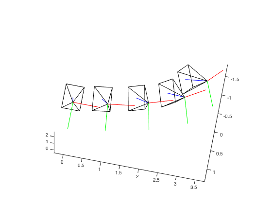
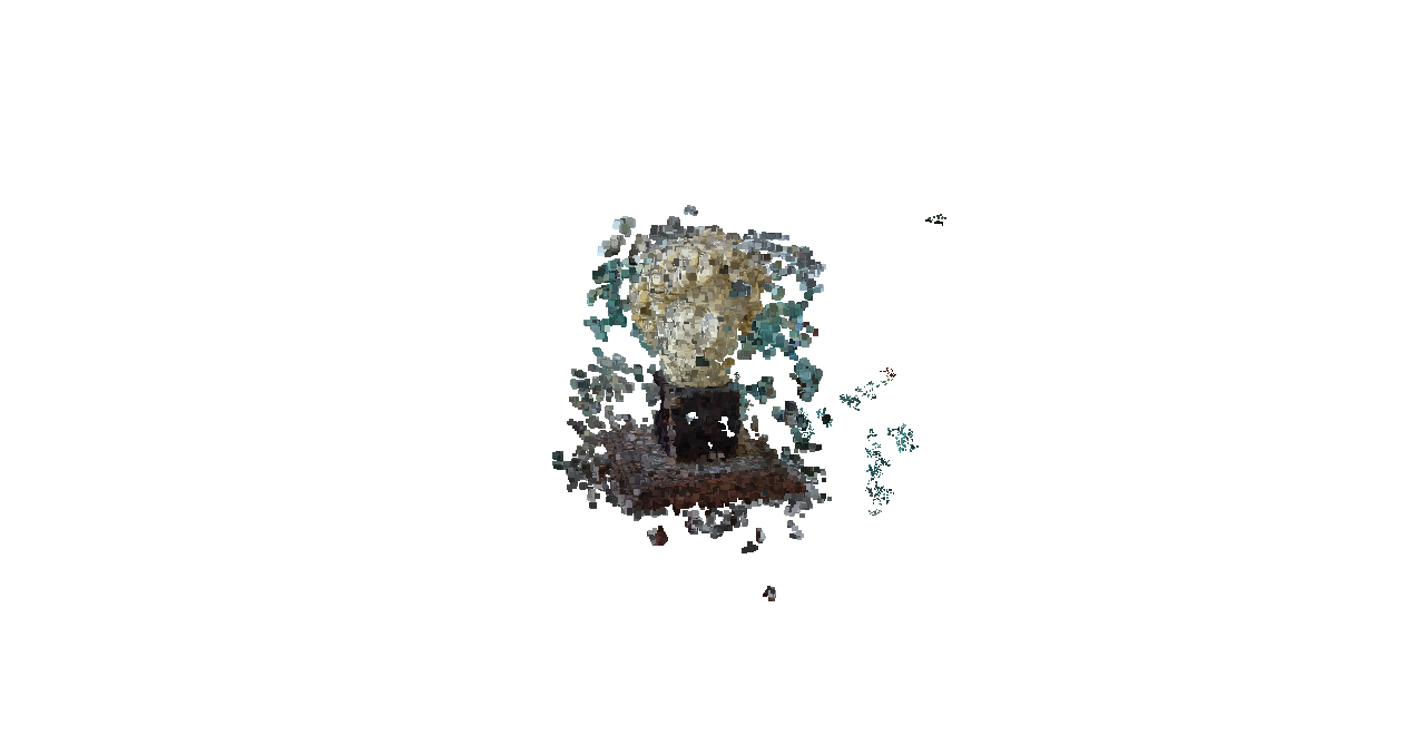
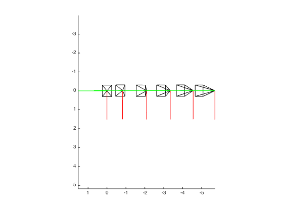
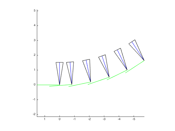
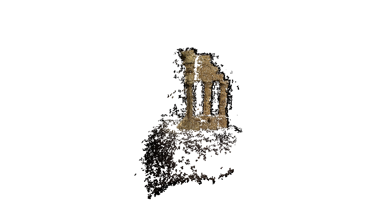
The lack of detail in the first dataset could be due to the lack of surface texture.
